PCB Linear Actuator

A fully integrated PCB linear actuator, with the motor driver, encoder and motor all on a single PCB. All designs are open source:
A video of it in action:
Motor Design and Validation
Design parameters of the motor were simulated with FEMM. There are not too many free parameters to optimize, but the goal is to find some off the shelf magnets which can be used, and to estimate the importance of things like air gap on motor performance.
The design ended up having the simplest possible winding layout (3 slots per pole), which maximized the amount of current carrying traces, while also having a high winding factor. 50mm * 10mm * 2mm magnets were used (which are a bit smaller in reality by ~0.5mm in each dimension), as they were easily available on EBay etc.
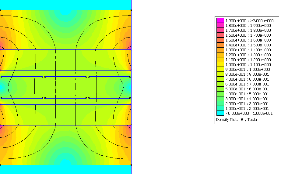
Flux visualization of magnetics simulation.
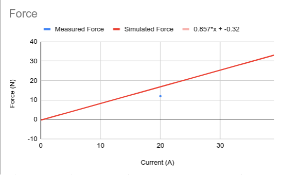
Force outputs of magnetic simulation. The force is very linear with respect to current, as there is no iron core to saturate. The simulated force seems reasonably accurate compared to the measured force, with likely the biggest discrepancy coming from the questionable quality of the magnets.
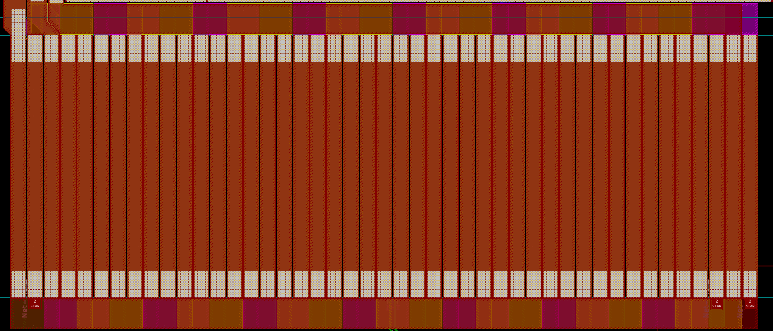
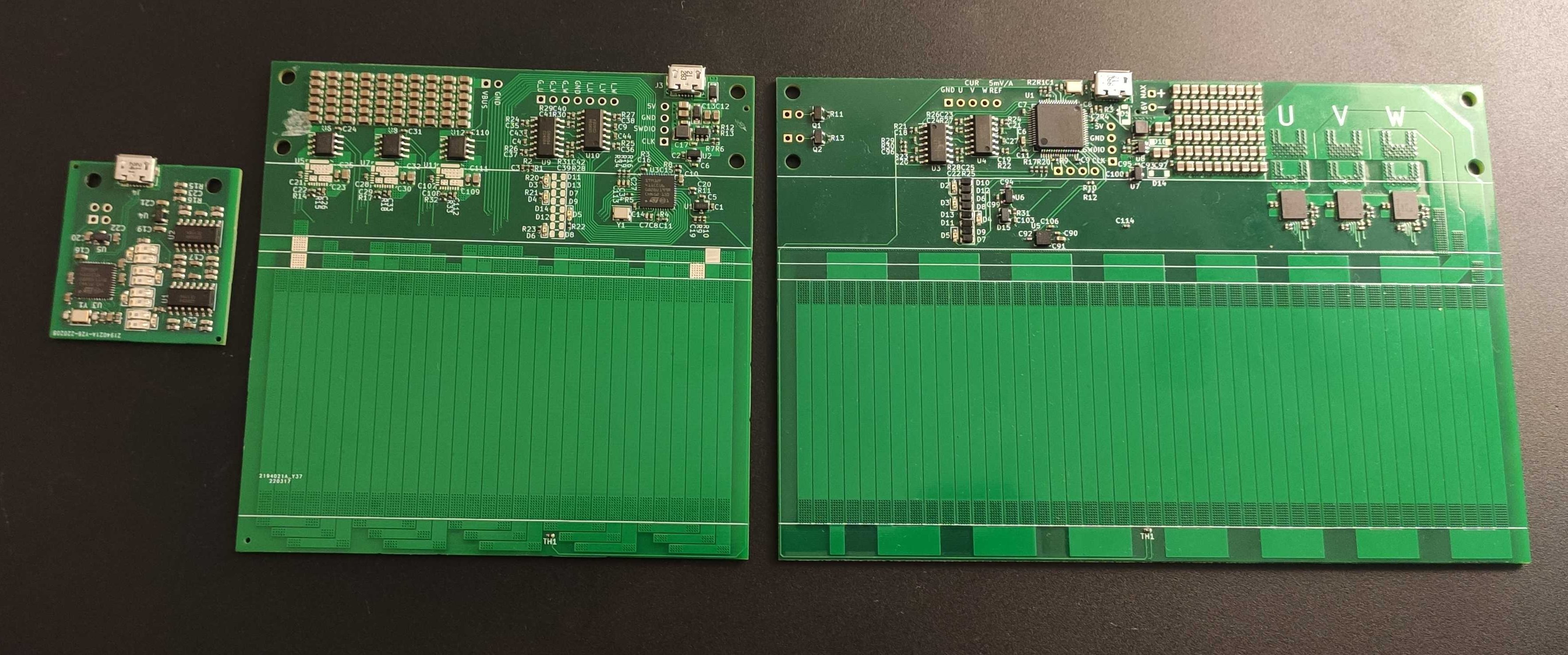
The motor itself is constructed using a 4 layer 2oz PCB (with 2oz inner layers) from JLCPCB. The motor itself uses all 4 layers to effectively get 8 oz of copper. At the end turns, each phase uses a single layer, with the last one used as the star point.
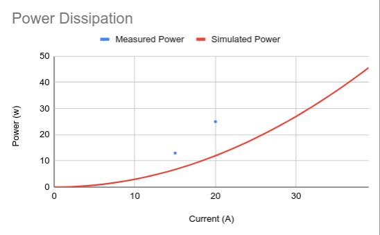
It appears the empirical power dissipation is approximately twice as high as the estimates. Not entirely sure why, but my best guess is a combination of copper being slightly thinner than 75um per layer in reality, as well as the power dissipation of the drivers.
There is space to attach a small heatsink on top of the PCB, and a continuous power dissipation of 25W doesn’t seem to cause any issues.
Motor Assembly
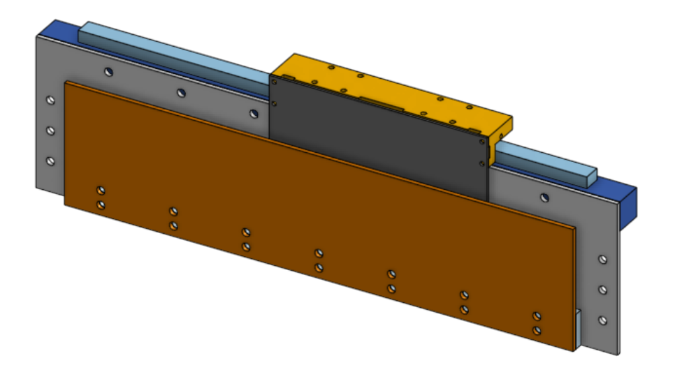
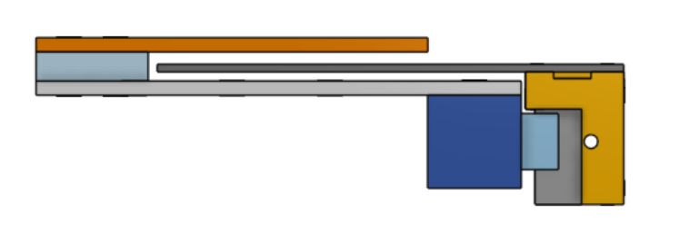
The motor is constructed with two mild steel plates, sandwiching an aluminium spacer. Parts were made at SendCutSend, which was quite fast and reasonably priced. The magnets (not shown in CAD) are simply just placed on the steel plates. No additional attachment required. Assembly is quite tricky due to the strength of the magnet, but can be done with some non-magnetic spacers (I used scrap FR4 PCBs).
The linear rail is mounted to the bottom plate with a 20mm x 20mm aluminium extrusion. The motor PCB is attached to the rail blocks with a 3d printed mounting block.
Motor Driver
I used smart power stage ICs (also known as DrMOS) for the power stage (specifically the FDMF3170). This is a bit of an unconventional use for these chips, but it integrates the high side and low side MOSFETs, both gate drivers, temperature and current sensing and bootstrap circuitry into a single chip which only requires a few passives. This made the power stage layout a breeze, and also allows for operation at very high switching frequencies (up to 1Mhz).
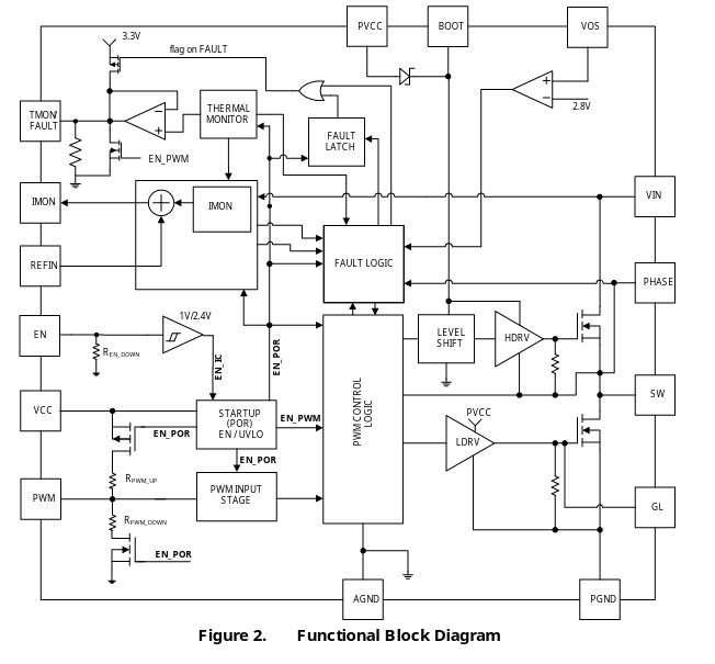
Block diagram of the FDMF3170 power stage. You really get quite a lot for just a few bucks!
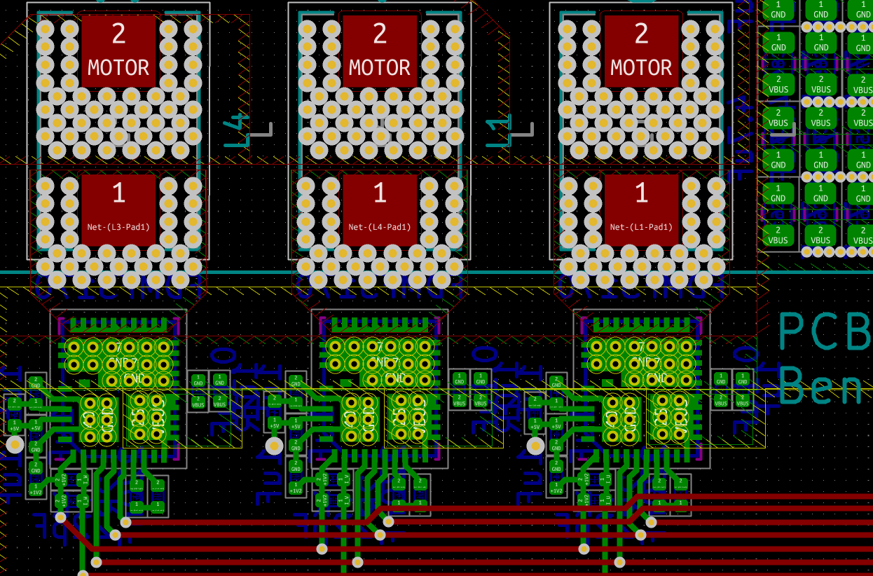
The power stage layout, which is now pretty boring as each phase is just a single chip.
However, the top and bottom FETs are not balanced, with the bottom side having much lower RDSon than the top side (These are designed for 12V to ~1V switching converters after all). This means the SVM algorithm needs to be slightly modified, away from the traditional alt-rev SVM (where during the zero period, the 111 and 000 phase vectors are both used alternately to balance heat dissipation between the top and bottom sides, under the assumption that the switches are the same). The modified scheme only uses the 000 phase vector, which minimizes resistance losses.
An additional challenge of driving this type of linear motor is that the inductance of the motor is very low, as there is no iron core. This would necessitate an extremely high switching frequency. I decided not to do this (mostly due to running out of timer resolution), and instead added a small inductor (470nH) in series with the motor leads to increase the inductance. This increases the resistance losses, but it is quite small.
The driver is controlled by a STM32F412 microcontroller, and switches at 200khz with the control loop running at 8khz.
Encoder
The encoder is a reflective IR sensor with 8 channels. 4 channels are used to build a quadrature encoder, with differential signals for the sin and cosine phases. The other 4 channels are for 2 other non-differential quadrature tracks with different frequencies. This theoretically enables for absolute positional encoding (as the phase multiple can be computed using the phase difference between the 3 quadrature signals), but I haven’t implemented this yet.
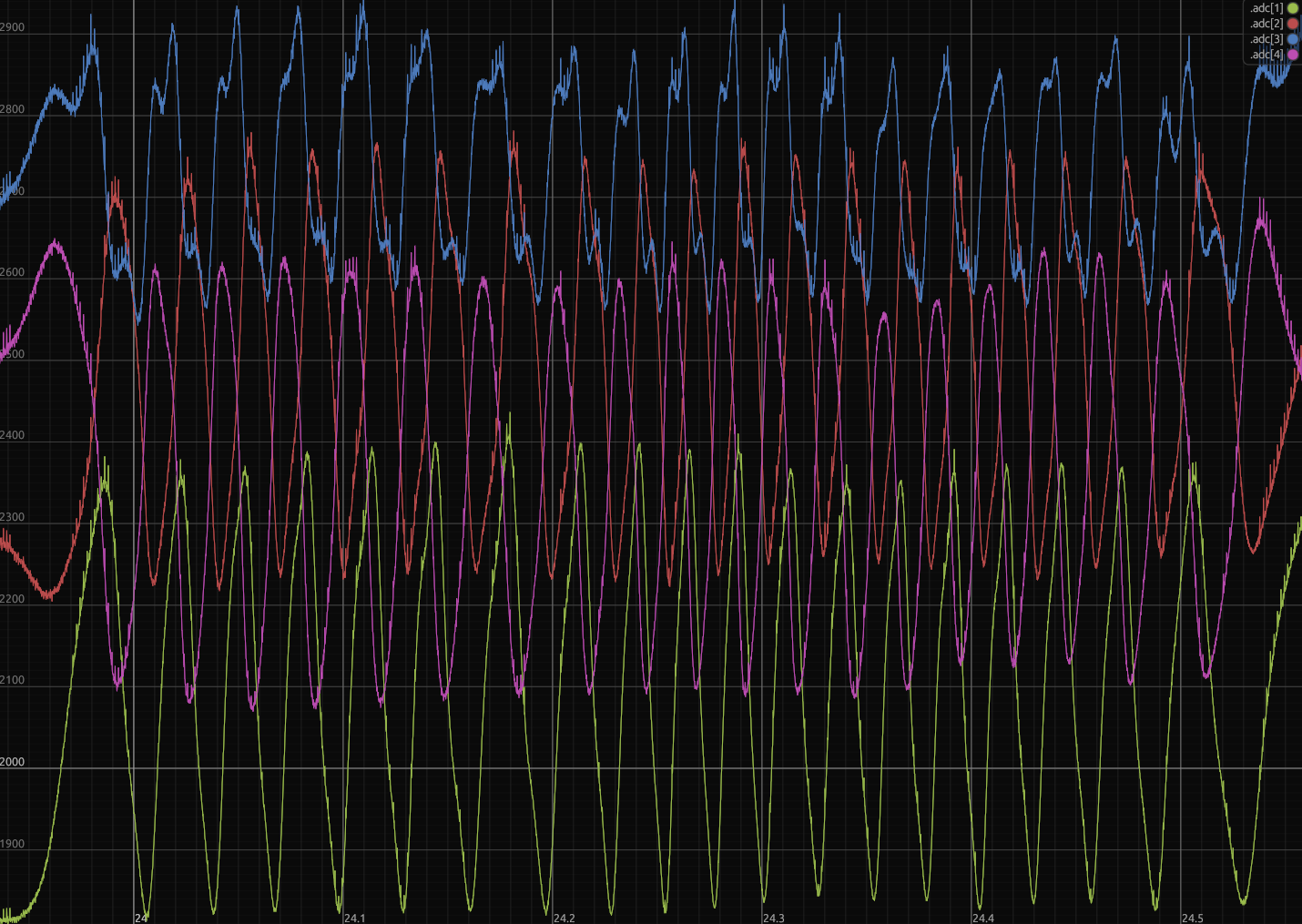
The signals are a bit messy due to some crosstalk between channels, as well as some switching noise, but achieves approximately 10um peak to peak noise after decoding.
Embedded Software
Firmware is written entirely in Rust, using the RTIC framework. The main task is driven by a 8khz timer interrupt, which triggers an ADC scan and DMA requests to read all encoder and motor driver inputs. The DMA completion interrupt triggers a software task which computes the control loop, which sets the PWM duty cycles. A background task handles the USB communications, which uses any remaining CPU time.
One interesting feature of the firmware is in the communication protocol. Rather than hand coding getter and setter methods for each parameter, I wrote a crate called remote-obj to essentially create getter and setters automatically for nested structs and enums using a proc-macro.
Combined with a way to compactly encode the parameters with synchronized metadata between the host and device, this enables an on-device oscilloscope which can sample variables at up to the control loop frequency (up to 16 values at 8khz). The data is buffered on-device using a neat lockless ring buffer which holds packets contiguously in memory for easy access.
This data is then sent to the host over USB CDC ACM. Even though there is no latency/throughput guarantee when using USB bulk endpoints, I’ve found it to be quite fast and low latency, reliably achieving up to 8 mbps out of the theoretical 12 mbps of the USB full speed PHY built in to the STM32, while also having <10ms of latency.
Host Software
The host software is also written in Rust, using the egui framework. Most of the complexity is involved with handling the USB communication in a low latency way. In particular, dedicated threads drive reading from and writing to the USB endpoints.
To create a low latency USB stream, the easiest way is to continuously send read requests in a loop, and have the USB device terminate the transfer when the device runs out of buffer (using a non-full packet). Importantly to have high throughput is to immediately send another read request when another completes, which keeps the bus busy. The results are communicated over channels to other threads.
The software uses runtime reflection facilities provided by remote-obj to view and set parameters (and to know what parameters are available to view and set).
Performance
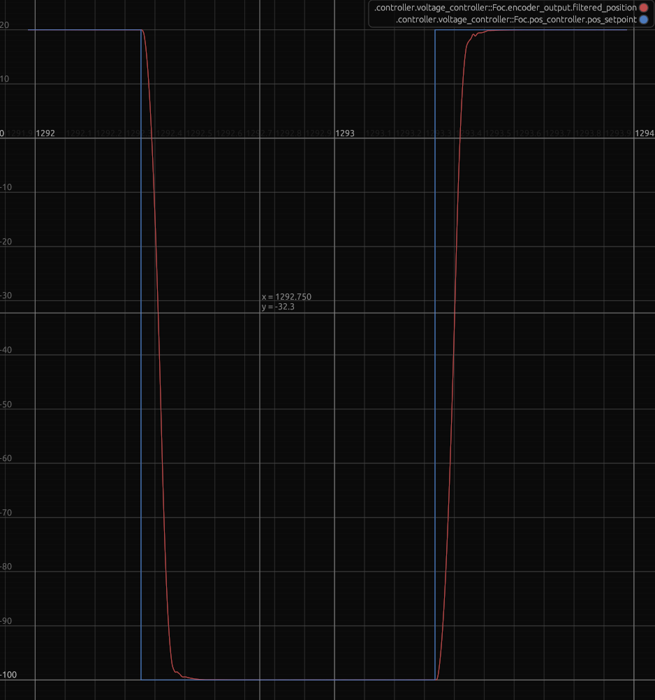
100mm moves take under 200ms. (each horizontal tick is 100ms)

From the velocity plot above, it takes approximately 60ms to achieve 2100mm/s, for an acceleration of around 35m/s^2, and it takes approximately 40ms to decelerate back to 100mm/s, for deceleration of around 50m/s^2.
Better performance can likely be achieved with higher currents, but I’m limited by the quite low OCP of my power supply (which is a macbook charger…)
Previous Versions and Future
It took a few hardware revisions to get to this point, and I’ll probably do one more before I call this project “done”
Get in touch if you would like a few assembled boards from the next revision! (contact info in the footer)